Thermodynamics of CAES
August 9, 2014.
A couple of notes about conventional CAES
Conventional CAES is an energy storage technology that has been around for several decades. It is interesting because although there are two plants currently functional and in existence, no new plant has been built in the last 20 years, despite the fact that both of the existing plants remain open and continue to function economically. This can probably be attributed to high CAPEX costs for CAES and other cheaper generation technologies which represent similar or better investments, added with an uncertainty of how to class CAES and view its efficiency.
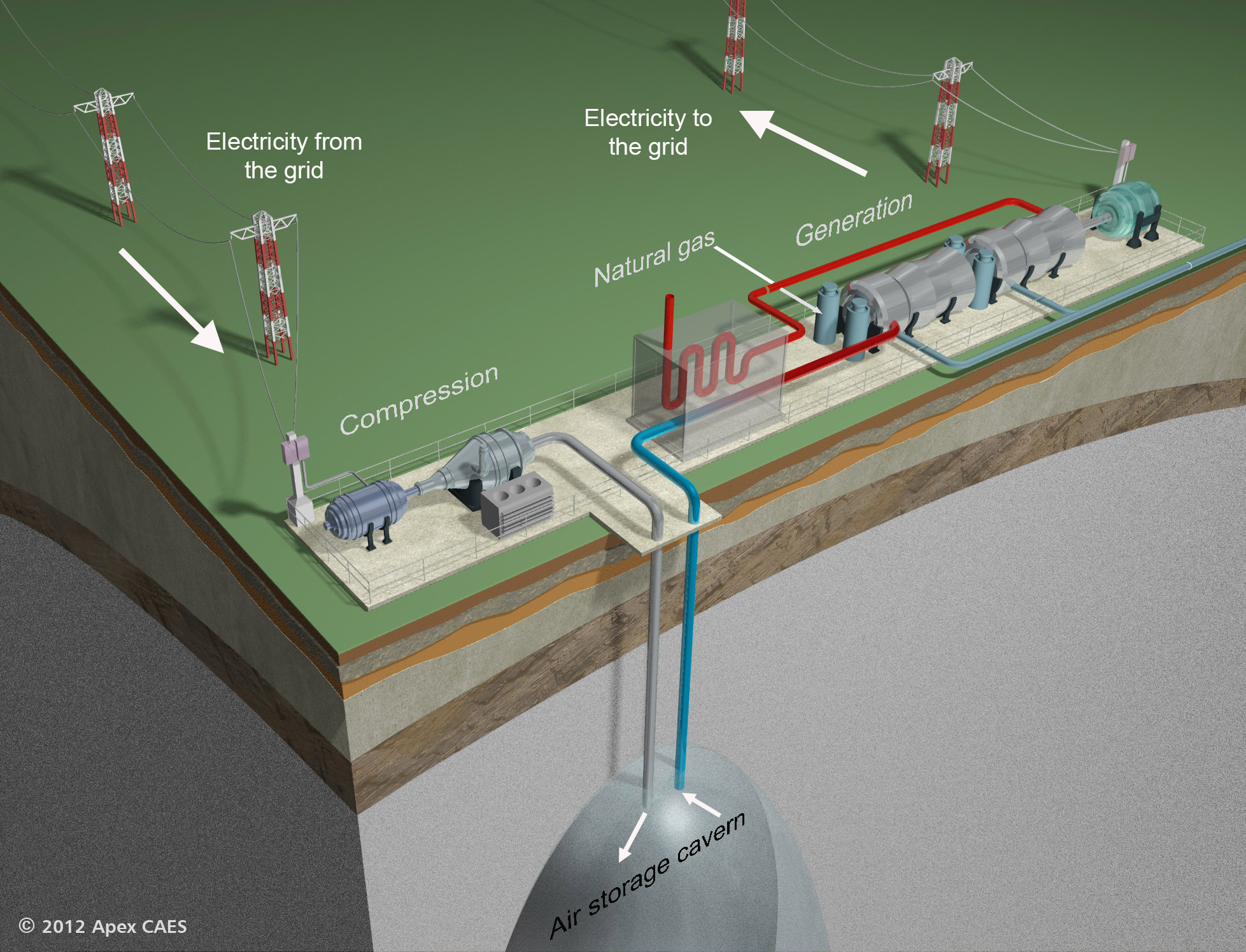
Figure 1: The convential diabatic CAES system with a recuperator. Natural gas is mixed with the compressed air in the generation unit.
Calculating the efficiency of CAES facilities is perhaps not as straightforward as it first seems. The McIntosh CAES plant uses 1 kWh of natural gas and 0.69 kWh of electricity to produce 1 kWh of peak electricity. The energy efficiency in terms of energy-output/energy-input is then around 59%, i.e. quite low for an energy storage technology. However, if instead you consider that the efficiency of a conventional thermal gas generator is around 40%, you would only ever get 0.4 kWh of electricity out of the 1 kWh of gas used in the CAES plant. This makes the efficiency look much better, as now it effectively appears as though you put 0.69 kWh + 0.4 kWh = 1.09 kWh of electricity in and you get 1 kWh of electricity out, giving an efficiency of 92%. Conversely, another argument would be that the 1 kWh of electricity required 2.5 kWh of gas to generate, and hence the energy input is 3.5 kWh of gas to produce 1 kWh of electricity, giving a much poorer efficiency of 29%.
The point of all this is that the “efficiency” values often quoted for CAES must be treated with caution and are generally not comparable with other storage technologies which input and output electricity only, as CAES plants are NEITHER purely energy storage NOR thermal generation, but in reality they represent a mix of both. I haven’t quite decided how to interpret this myself except that when considering CAES as an energy storage option, it is more important to consider from what source the electricity used in charging comes from than other energy storage technologies. For example, using CAES in the context where it would mainly have an electricity-from-renewable input could be regarded as boosting the efficiency of gas generation and hence a good thing under these circumstances, whereas using CAES as a way to store fossil fuel generated electricity would seem like a bad idea. I don’t fully endorse this last statement, rather I’m just using it as an illustration…
CAES without the fossil fuels
CAES concepts which remove fossil fuel combustion are promising new energy storage technologies that store mechanical work in both compressed air and heat and returns it as mechanical work at a later stage (the mechanical work is usually converted from electricity by a motor and back to electricity by a generator). These fuel-free CAES systems are usually classed as either Isothermal vs Adiabatic CAES.
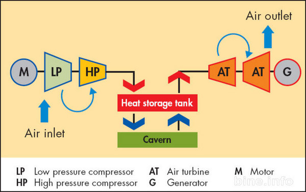
Figure 2: The general principle for the Fuelless CAES concept.
In most designs the compression and expansion can be near-isothermal or close to adiabatic – both involve a temperature rise during compression and require separate heat storage. True isothermal compression would be the ideal case it wouldn’t require a separate thermal store, as heat would essentially be stored at ambient temperature in the surrounding environment, however any compression approaching this would be too slow to be practical. It is a little confusing that near-isothermal compression is often dubbed as “isothermal”. Isothermal CAES designs typically propose the use of a near-isothermal compression in which a thermal fluid spray is injected into the compression chamber and which reduces the temperature rise experienced by the air during the compression. This warm thermal fluid must be stored in a separate heat store. Adiabatic CAES designs propose that the compression produces a temperature rise close to the adiabatic temperature rise. The compression heat must then be stored at a much higher temperature than the near isothermal case. This heat is usually removed and stored separately from the compressed air. It is important to note that the energy is stored both mechanically and as heat, and it is only the effective recombination of these two parts that can lead to an efficient system.
Thermodynamic work is path dependent
This has quite a profound consequence on the design of a fuelless CAES system: to maximise the work output of a CAES system the discharging process should follow the exact and opposite path of the compression process. Designs in which this is not the case are intrinsically inefficient and analyses of their efficiency are not reflective of a fundamental limit of the fuelless CAES concept (though this does not mean that they could not ever make economic sense). I have however read a number of academic articles that anaylse systems in which the expansion process is not the same as the compression and then seem to imply general conclusions about the system efficiency, which is misleading. Another common misconception is that the second law of thermodynamics imposes some fundamental limit less than 100% on the efficiency of the system. I think that this comes from a misapplication of the Carnot efficiency for a heat engine, as there is a re-heating element associated with the expansion part of the fuelless CAES process. What the second law of thermodynamics actually states is that even in the limiting case that a reversible system is designed with perfect lossless components, the round trip efficiency cannot be greater than 100%. In a perfect well designed system, the compression takes mechanical work and converts it into potential energy AND takes in heat at ambient temperature and moves it to a high temperature heat store. For perfect intercooling and an ideal gas the heat moved is equal to the work in, discounting the energy stored in the cold compressed air. Of course, this is not a violation of the first law as heat is also taken in with the ambient air. If one were to expand this cold air you would get some work out and you would have moved more heat than the net work put in. This is of course the principle of a heat pump and it is commonly known that these can have COP’s greater than 1. The expansion part then involves recombining the stored heat and the cold compressed air. With no heat losses and perfect inter-heating the compressed air is re-heated to exactly the same temperature as it was after the compression. And finally if the expansion is exactly the reverse of the compression the work out will be the same as the work in for the compression. Heat will be rejected at the ambient temperature with the compressed air. This perfect system does not solely convert heat into work, does not result in a net movement of heat from a lower temperature to a higher temperature without the addition of work and does not result in a net decrease of the entropy of the universe. Hence it is not disallowed by the second law. Of course in practice the second law means that no process is perfect and each real component will introduce losses, and so practically the second law means that the limiting efficiency value of the perfect fuelless CAES process is 100%.
So now on to exergy and CAES. As a physicist I had never come across exergy before I thought as an engineering PhD student that I’d better look at an engineering thermodynamics textbook. It is a very powerful concept. The exergy of a system is a measure of the available work extractable between that system and the “dead state”, which is just the ambient environment. It can be formulated by considering the energy and entropy changes in a general process that involves changes in the enthalpy of a flow through a system, internal energy changes, work in/out and heat flow in/out to the ambient. By simultaneously accounting for both energy and entropy, exergy accounts for the quality of different forms of energy. A good introduction to the concept can be found in most Engineering Thermodynamic textbooks (i.e. Fundamentals of Engineering Thermodynamics by Moran and Shapiro) and there are some good online resources like this. It is an incredibly useful concept in system analysis that accounts for the both the first and second laws simultaneously. In the analysis of engineering systems it allows the irreversibility of different system components to be analysed. In the design of a CAES system this is invaluable as it allows the “exergy destruction” in each component (heat exchangers, compressors, expanders etc) to be estimated. It also allows the maximum extractable work from the system to be easily calculated, which gives an indication of the reversibility of a perfect design.
As an example let’s do an exergy analysis of a CAES system with perfect lossless components with two compression stages and one expansion stage. This will illustrate that the maximum work out of the single expansion stage is less than the compression work put in, and crucially it illustrates where the remaining work is lost. The high pressure air store is considered isobaric so there is no increase in pressure as air is added to the store. The gas is an ideal gas with a constant specific heat capacity. With an isochoric store the equations just become a little more complicated and require more integration.
Consider a system with a 2-stage compression and single stage expansion as illustrated below.
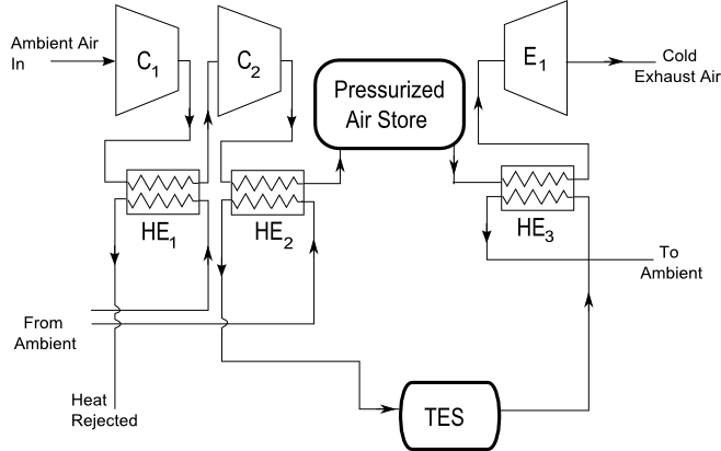
Figure 3: Example asymmetric fuelless CAES system
Each compression increases the pressure ratio by a factor of r, so the total work input in the compression is given by Equation 1. \begin{eqnarray} \frac{W_{comp}}{m} & = & c_p T_0 ((\frac{P_2}{p_1})^{\frac{\gamma-1}{\gamma}} - 1) + c_p T_0 ((\frac{P_3}{p_3})^{\frac{\gamma-1}{\gamma}} - 1) \\ & = & 2 c_p T_0 (r^x-1) \tag{1} \end{eqnarray} \begin{equation} T_{max} = T_0 r^x \tag{2} \end{equation}
where $r=\frac{P_2}{P_1}=\frac{P_3}{P_2}$ and $x=\frac{\gamma-1}{\gamma}$. The heat removed in each inter-cooling stage is: \begin{equation} \frac{Q}{m} = c_p(T_{max}-T_0) = c_p T_0 (r^x-1) \tag{3} \end{equation}
The maximum temperature to which the air can be heated without extra heat or work in before the expansion is the same as the temperature from the compression, so the work out of the single stage expansion is: \begin{eqnarray} \frac{W_{exp}}{m} & = & c_p T_{max} ((\frac{P_1}{P_3})^{\frac{\gamma-1}{\gamma}}-1) \\ & = & c_pT_{max}(r^{-2x}-1) \\ & = & c_pT_0(r^{-x}-r^{x}) \tag{4} \end{eqnarray}
It has a negative value for r>1 which means work is done by the system. The outlet temperature of the turbine is colder than the ambient as the pressure ratio for the expansion stage is r2 rather than r for each expansion. It is given by: \begin{equation} T_{out} = T_{max}r^{-2x}=T_0 r^{-x} \tag{5} \end{equation}
The work that could be extracted from this cold ambient pressure air can be calculated by considering its exergy. The exergy associated from a flow of heat from some temperature to the ambient T0 is given by: \begin{equation} B_{heatflow} = Q(1-\frac{T_0}{T}) \tag{6} \end{equation}
However as the heat is flowing from the body of air it is cooling down so we write: \begin{eqnarray} \delta B_{airout} & = & \delta Q (1-\frac{T_0}{T}) \\ & = & mc_p\delta T (1-\frac{T_0}{T}) \tag{7} \end{eqnarray}
Integrating this from T = Ti to T = T0 gives: \begin{eqnarray} B_{airout} & = & mc_p(T_i-T_0-T_0 \mbox{ln}\frac{T_i}{T_0}) \\ & = & mc_pT_0(\frac{T_i}{T_0}-1-\mbox{ln}\frac{T_i}{T_0}) \tag{8} \end{eqnarray}
Putting in the value for Ti gives: \begin{eqnarray} B_{airout} &=& mc_pT_0(\frac{T_{out}}{T_0}-1-\mbox{ln}\frac{T_{out}}{T_0}) \\ &=& mc_pT_0(r^{-x}-1-\mbox{ln}r^{-x}) \tag{9} \end{eqnarray}
There is also heat left over from the compression, as only the heat from one intercooling stage could be used before the expansion (because no net heat will flow between two identical temperatures). The exergy associated with this leftover heat can also be calculated in the same manner as: \begin{eqnarray} B_{heatleft} & = & mc_pT_0(\frac{T_{max}}{T_0}-1-\mbox{ln}\frac{T_{max}}{T_0}) \\ & = & mc_pT_0(r^{x}-1-\mbox{ln}r^x) \tag{10} \end{eqnarray}
So now we have accounted for all the work in that went into the compression. With a single expansion stage extracting the work out the efficiency is limited to: \begin{equation} \frac{r^{-x}-r^{x}}{2(r^x-1)} \tag{11} \end{equation}
To check we have accounted for all the work into the system we sum the work out and the exergy associated with the cold outlet air and the leftover compression heat.
\begin{eqnarray} & & \frac{W_{exp}}{m}+\frac{B_{heatleft}}{m}+\frac{B_{airout}}{m} \\ & = & -c_pT_0(r^{-x}-r^x)+c_pT_0(r^{-x}-1-\mbox{ln}r^{-x})+c_pT_0(r^x-1-\mbox{ln}r^x) \\ & = & c_pT_0(2r^x-2) \\ & = & \frac{W_{comp}}{m} \tag{12} \end{eqnarray}
Low and behold the total is the compression work! Therefore we can see where all the work into the system has gone. Even with perfect isentropic lossless components it is not possible to extract all of the 2-stage compression work through a single expansion. The missing work has been accounted for as leftover stored heat and the exit loss from the turbine.
The point of this example is to give a small insight into the power of exergy and encourage its use in both CAES analyses and for informing designs.